


|
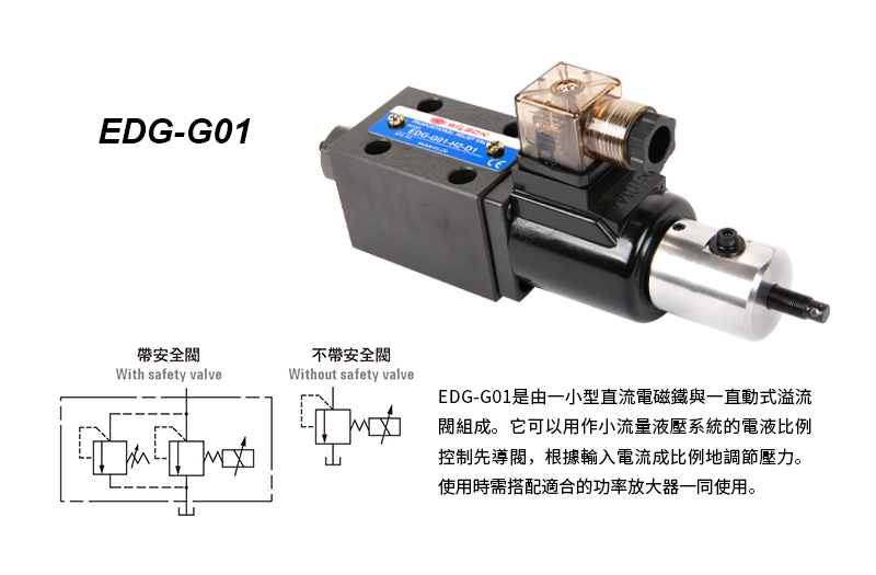
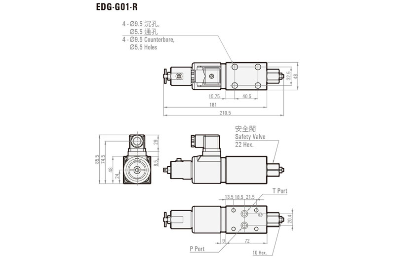
EDG-G01
Electro-Hydraulic Proportional Pilot Relief Valve |
Product details
ORDER CODES:
|
EDG - |
G01 - |
H2 - |
D1 - |
R |
|
Model
Name |
Thread
Connection |
Pressure
Adjusting Range |
Coil
Resistance |
Safety
Valve |
|
EDG |
G01
: 1/4" |
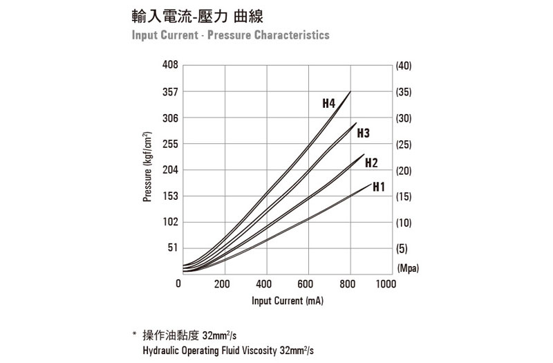
H1
: 10~143 kgf/cm2 ( 1.0~14 Mpa ) H2
: 15.3~214 kgf/cm2 ( 1.5~21 Mpa ) H3
: 15.3~286 kgf/cm2 ( 1.5~28 Mpa ) H4
: 20~357 kgf/cm2 ( 2.0~35 Mpa ) |
D1
: 10Ω D2
: 20Ω |
R
: with safety valve none
: without safety valve |
SPECIFICATION:
|
Model |
EDG-G01 |
|
Max.
Flows |
1.2
l/min |
|
Pressure
Adjusting Range |
H1
: 10~143 kgf/cm2 ( 1.0~14MPa ) H2
: 15.3~214 kgf/cm2 ( 1.5~21MPa ) H3
: 15.3~286 kgf/cm2 ( 1.5~28MPa ) H4
: 20~357 kgf/cm2 ( 2.0~35MPa ) |
|
Rated
Current |
800
mA |
|
Coil
Resistance |
10Ω
or 20Ω ( 20°C ) |
|
Magnetic
Hysteresis |
<3% |
|
Repeatability |
<1% |
|
Amplifier
No. |
TW2085 |
|
Weight |
1.6
kg |
* Note: Value when a
WILSON amplifier TW2085 is used (with dithering).
BUNDLED ACCESSORIES:
|
Model |
Mounting Bolts |
Q'ty |
|
EDG-G01 |
M5
x L45 |
4 |
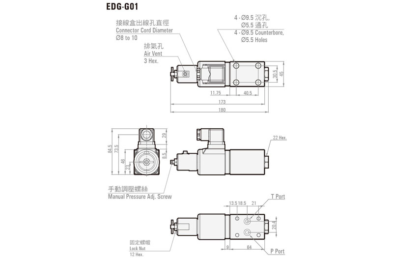
HANDLING:
1. Air Bleeding : To enable proper
pressure control, loosen the air vent when starting up the pump in order to
drain any air from the pump, and fill the insideof the solenoid with hydraulic
operational fluid. The position of the air vent can change by loosening the M4
screw and rotating the cover.
2. Mounting Method : Mounting on a
vertical surface causes minimum pressure to increase by 2 kgf/cm2
(0.2 Mpa).
3. Manual Pressure Adjusting Screw : For
the initial adjustment or when there is no input current to the valve due to an
electrical problem or some other reason, valve pressure can be increased by
rotating the manual adjustment screw clockwise (rightward). Normally, the
manual adjusting screw should be rotated back fully to the left
(counterclockwise) and secured with the lock nut.
4. Please minimize the oil pressure in
the return line, and make sure that the output of independent tube must be
under the oil surface in the tank.
5. Minimum Relief Flow Rate : A small
flow rate can cause setting pressure to become unstable. Use a flow rate of at
least 0.3 l/min.
6. Load Capacity : When using this valve
to control direct circuit pressure, make sure the load volume (P port side
volume) is at least 40 cm3.
7. Use an operating fluid that conforms
to the both of the following.
Oil temperature: -20 to 70°C.
Viscosity: 12 to 400mm2/s.
The recommended viscosity range is 15 to 60mm2/s.