


|
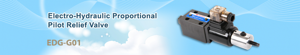
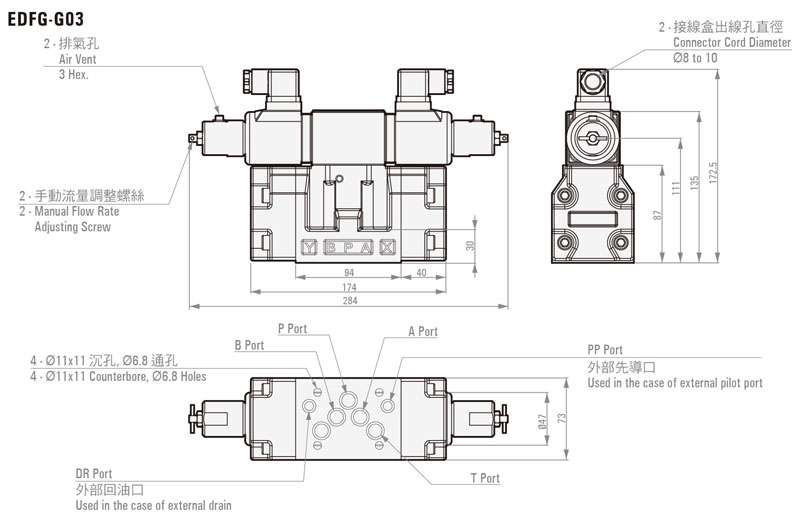
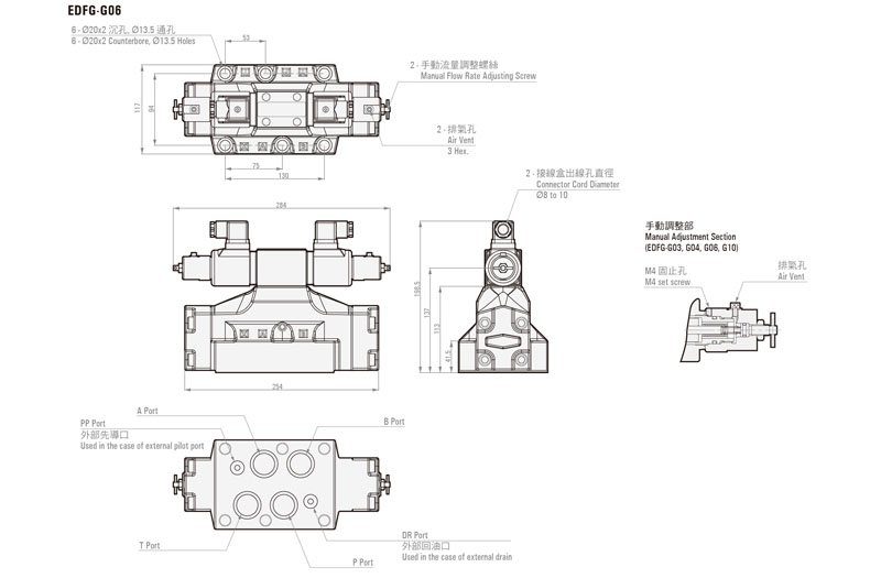
EDFG-G01, G03, G04, G06
Electro-Hydraulic Proportional Flow & Directional Control Valve |
Product details
ORDER CODES:
|
EDFG - |
G03 - |
3C2 - |
XY |
|
Model
Name |
Thread
Connection |
Spool
Type |
Drain
Type |
|
EDFG |
G01
: 1/4" G03
: 3/8" G04
: 1/2" G06
: 3/4" G10
: 1-1/4" |
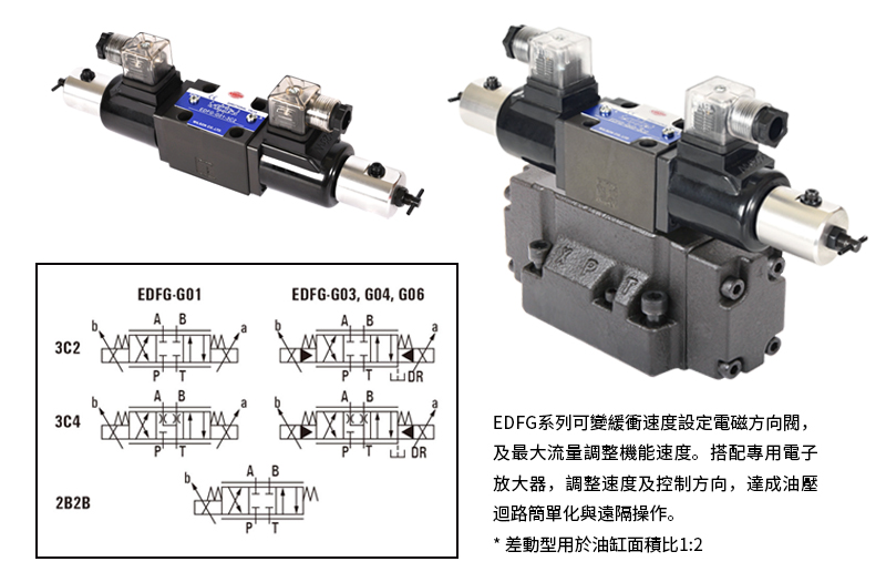
3C2 3C4 2B2B |
XY
: external pilot and external drain *
EDFG-G01 is not applicable |
SPECIFICATION:
|
Model |
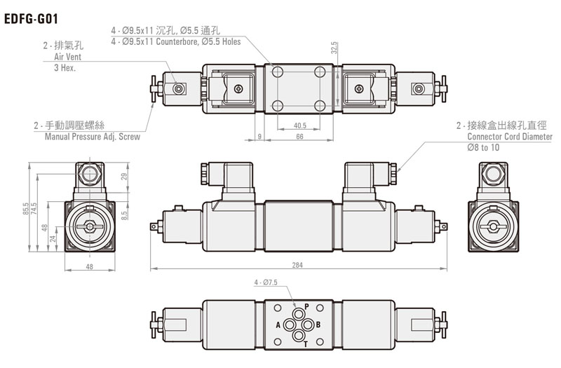
EDFG-G01 |
EDFG-G03 |
EDFG-G04 |
EDFG-G06 |
|
Max.
Operational Pressure |
225 kgf/cm2 ( 25 MPa ) |
|||
|
Rated
Flow |
10/25
l/min |
40/80
l/min |
140
l/min |
250
l/min |
|
Pilot
Pressure |
- |
>10
kgf/cm2 (1.0 MPa) |
>10
kgf/cm2 (1.0 MPa) |
>10
kgf/cm2 (1.0 MPa) |
|
Pilot
Flow |
- |
>2
l/min |
>3
l/min |
>5
l/min |
|
Allowable
Back Pressure of T port |
25.5
kgf/cm2 ( 2.5 MPa ) |
25.5
kgf/cm2 (2.5 MPa) |
||
|
Rated
Current |
850 mA |
|||
|
Coil
Resistance |
20Ω ( 20°C ) |
|||
|
Magnetic
Hysteresis |
<5% |
|||
|
Repeatability |
0.04
sec |
0.05
sec |
0.08
sec |
0.1
sec |
|
Amplifier
No. |
TW9820 series |
|||
|
Weight |
2.2
kg |
6.6
kg |
7.8
kg |
12.9
kg |
* Note:
1. Value when
pressure drop volume to P→A and P→B
is ΔP = 10 kgf/cm2 (1.0 MPa).
2. Indicates maximum
throughput volume value between each port.
3. Indicates
differential between the pilot port and tank port, or drain port.
4. Value when 0.1
second is assumed for the response time from zero to the rated flow volume.
5. Value when a
WILSON amplifier TW9820-2 is used.
6. Response time is
typical value for a supply pressure of 143 kgf/cm2 (14 MPa) and
fluid temperature of 40°C (kinematic viscosity: 40 mm2/s).
BUNDLED ACCESSORIES:
|
Model |
Mounting Bolts |
Q'ty |
|
EDFG-G01 |
M5
x L45 |
4 |
|
EDFG-G03 |
M6
x L35 |
4 |
|
EDFG-G04 |
M6
x L45 |
2 |
|
M10
x L50 |
4 |
|
|
EDFG-G06 |
M120
x L60 |
6 |
HANDLING:
1.
Air Bleeding : In order to ensure stable control, loosen the air vent and bleed
air from the valve before starting operation.
2.
T Port Piping : When configuring piping, ensure that the T port (pilot valve T port
for the G03, G04, and G06 sizes) is filled with operational fluid.
3.
Manual Adjusting Screw : For the initial adjustment or when there is no input current
to the valve due to an electrical problem or some other reason, the valve can
be operated and valve pressure can be increased by rotating the manual adjustment
screw clockwise (rightward). Normally, the manual adjusting screw should be
rotated back fully to the left (counterclockwise).
4.
Valve Mounting Orientation : Install the valve so the spool axis line is
horizontal.
5.
Combining with a Pressure Compensation Valve : Use of the optional pressure compensation
kit is recommended when higher precision flow rate control is required or in
high-pressure applications.
6.
If pilot pressure exceeds 92 kgf/cm2 (9 MPa) use a modular type P
port reduction valve (MBRV-02-P-1) at a setting of 20 kgf/cm2 (2
MPa) (only for EDFG-G03, G04, G06).
7.
On a system that requires large brake pressure during deceleration or a system that
uses a vertical cylinder, equip a counter balance valve. Use a single rod, if the
rod exit is not slowed sufficiently, use a counter balance valve on the rod.
8.
Maintain hydraulic operational fluid contamination so it is at least Class 9.
9.
Use an operating fluid that conforms to the both of the following.
Oil temperature: -20 to 70°C.
Viscosity:
12 to 400mm2/s.
The recommended viscosity range is 15 to
60mm2/s.