


|
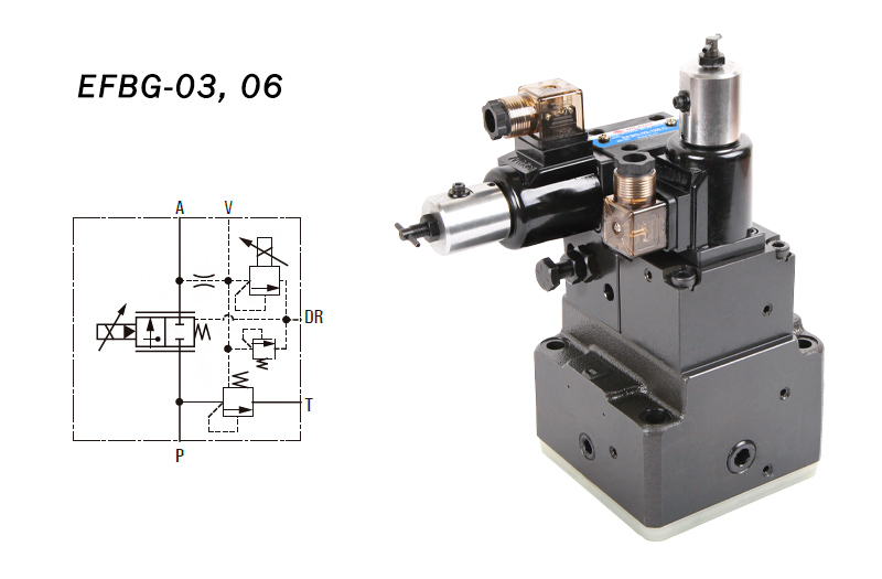
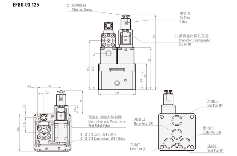
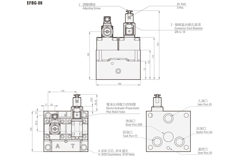
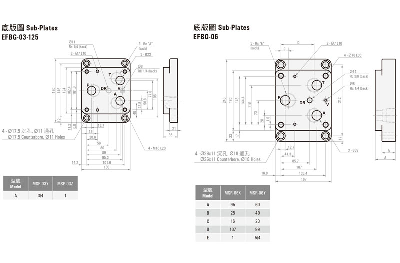
EFBG-03, 06
Electro-Hydraulic Proportional Relief & Flow Control Valve |
Product details
ORDER CODES:
|
EFBG - |
03 - |
125 - |
C - |
R2 |
|
Model
Name |
Thread
Connection |
Max.
Flow |
Max.
Operational Pressure |
Pressure
Control Range |
|
EFBG |
03
: 3/8" 06
: 3/4" |
60/125
l/min 250
l/min |
C
: 140 kgf/cm2 H
: 255 kgf/cm2 |
R1
: 12.2~71 kgf/cm2 (1.2~7Mpa) R2 : 14.3~143 kgf/cm2 (1.4~14Mpa) R3 : 16.3~214 kgf/cm2
(1.6~21Mpa) R4 : 16.3~255 kgf/cm2
(1.6~25Mpa) |
SPECIFICATION:
|
Model |
EFBG-03 |
EFBG-06 |
|
|
Max.
Operational Pressure |
255
kgf/cm2 ( 25 MPa ) |
||
|
Max.
Flows |
60/125
l/min |
250
l/min |
|
|
Flowing
System |
Flow
Adjusting Range |
1
~ 60 l/min 1
~ 125 l/min |
5
~ 250 l/min |
|
Internal
Resistance of This Valve |
5.1
kgf/cm2 ( 0.5 MPa ) <note1> |
7.1
kgf/cm2 ( 0.7 MPa ) <note1> |
|
|
Rated
Current |
800
mA |
||
|
Coil
Resistance |
20Ω
( 20°C ) |
||
|
Magnetic
Hysteresis |
<3%
<note2> |
||
|
Repeatability |
<1% |
||
|
Pressure
System |
Pressure
Control Range |
R1
: 12.2~71 kgf/cm2 (1.2~7 MPa) R2
: 14.3~143 kgf/cm2 (1.4~14MPa) R3
: 16.3~214 kgf/cm2 (1.6~21MPa) R4
: 16.3~255 kgf/cm2 (1.6~25MPa) |
|
|
Max.
Operational Pressure |
C
: 140 kgf/cm2 H
: 255 kgf/cm2 |
||
|
Rated
Current |
C
: 700 mA H
: 800 mA |
||
|
Coil
Resistance |
20Ω
( 20°C ) |
||
|
Magnetic
Hysteresis |
<3% |
||
|
Repeatability |
<1% |
||
|
Amplifier
No. |
TW9820
series |
||
|
Weight |
14
kg |
28
kg |
|
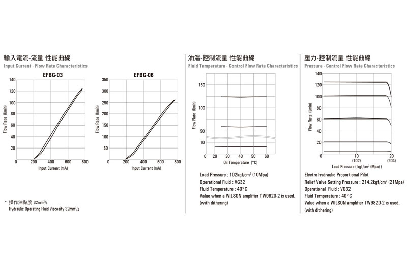
* Note:
1. Indicates the pressure differential between the valve P port and A
port.The left chart is complied with our standard electronic control circuit
board TW9820-2, and is the single valve test result.
2. Value when a WILSON amplifier TW9820-2 is used (with dithering).
3. These specifications apply to valves that include an
electro-hydraulic proportional pilot relief valve.
4. The maximum adjustment pressure is 255kgf/cm2 (25MPa max.)
for a valve that does not include an electro-hydraulic proportional pilot
relief valve. Factory default is minimum output 35.7kgf/cm2 (3.5MPa
max.) Set this value in accordance with the pressure of the hydraulic circuit
being used.
BUNDLED ACCESSORIES:
|
Model |
Mounting Bolts |
Q'ty |
|
EFBG-03 |
M10
x L75 |
2 |
|
M10
x L90 |
2 |
|
|
EFBG-06 |
M16
x L100 |
2 |
|
M16
x L135 |
2 |
HANDLING:
1. Air Bleeding : In order to ensure
stable control, loosen the air vent and bleed air from the valve before
starting operation.
2. Manual Adjusting Screw : For the
initial adjustment or when there is no input current to the valve due to an
electrical problem or some other reason, pressure or flow rate can be increased
by rotating the manual adjustment screw clockwise (rightward). Normally, this
adjusting screw should be returned completely to its original position and
secured with the lock nut.
3. Please minimize the oil pressure in
the return line, and make sure that the output of independent tube must be
under the oil surface in the tank.
4. Safety Valve Setting Pressure : For a
safety valve without an electro hydraulic proportional pilot relief valve,
safety valve pressure is set to minimum pressure 35.7kgf/cm2 (3.5Mpa
max.) In the case of a safety valve with an electrohydraulic proportional pilot
relief valve, the safety valve setting pressure is set to the minimum
adjustment pressure plus 15.3kgf/cm2 (1.5Mpa). When actually using
the valve, adjust in accordance with hydraulic circuit pressure.
5. Minimum Relief Flow Rate During
Pressure Control : Setting pressure can become unstable when the relief flow
rate to the valve's T port is small. Because of this, use a relief flow rate of
at least 10 l/min with a nominal diameter of 03 or 06.
6. Valve Mounting Orientation : When an
electro-hydraulic proportional pilot relief valve main valve is mounted on a
vertical surface with the pilot relief valve part facing downwards make it
difficult to bleed air from the pilot relief valve. Because of this, you should
not use this type of mounting orientation.
7. Use an operating fluid that conforms
to the both of the following.
Oil temperature: -20 to 70°C.
Viscosity: 12 to 400mm2/s.
The recommended viscosity range is 15 to 60mm2/s.